.png)
The steering system went from disassembly to a welded, mounted wheel; the rear suspension got its final shock mounts and a toe/camber correction; and the tie rods got fabricated from scratch. Oh — and we ate very well.
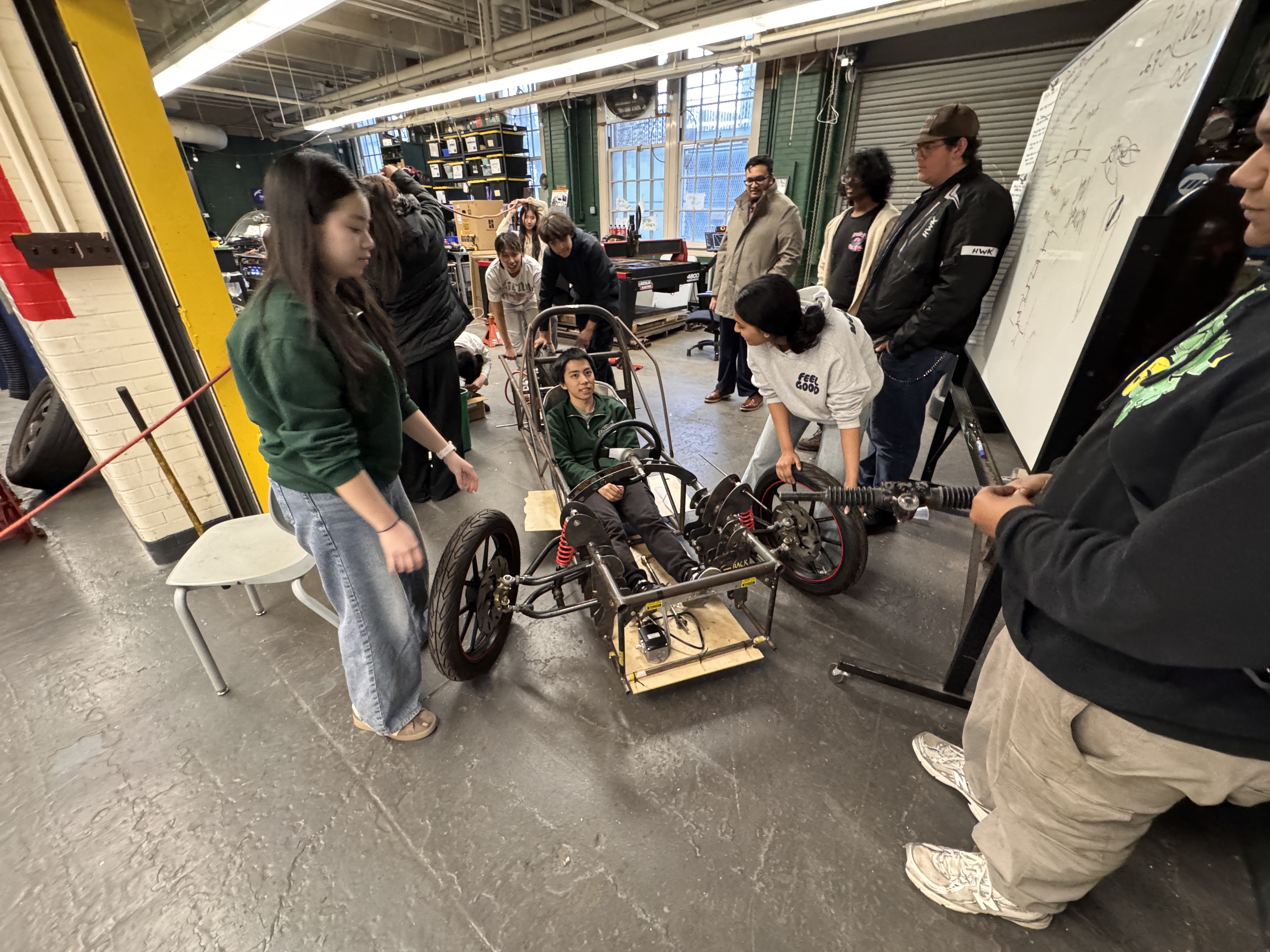
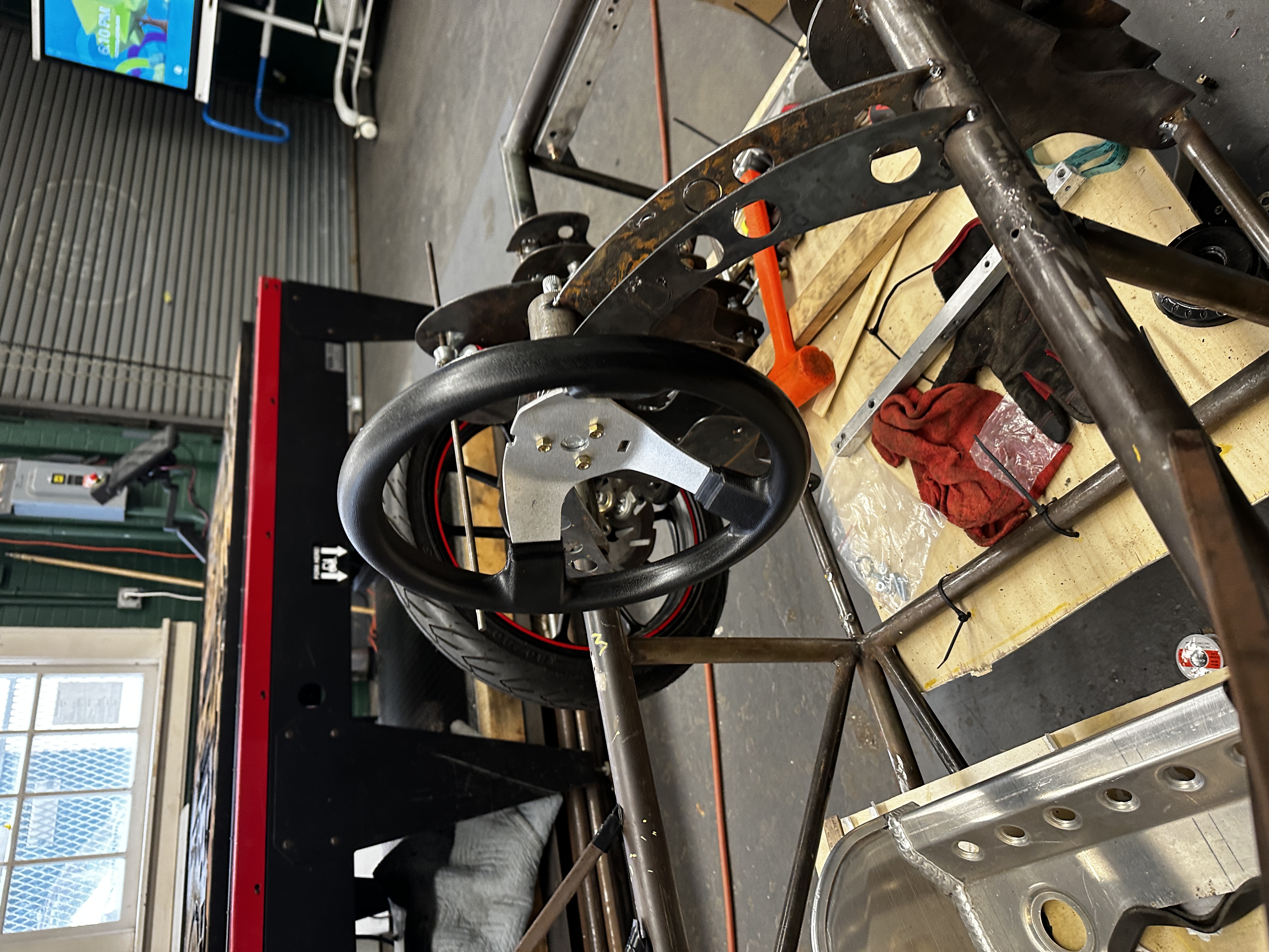
RACK, SHAFT & WHEEL — ALL IN ONE SESSION
We started by pulling the rack-and-pinion assembly apart completely. The input shaft was chucked on the Colchester lathe and machined down to accept the new universal joint on the steering shaft — clean, concentric, correct. No shimming, no guessing. The steering wheel mounting bracket was designed in CAD, plasma cut, and tack welded into final position — steering wheel and bearing plate located and locked. The column is now spatially committed; final welds come after geometry sign-off.
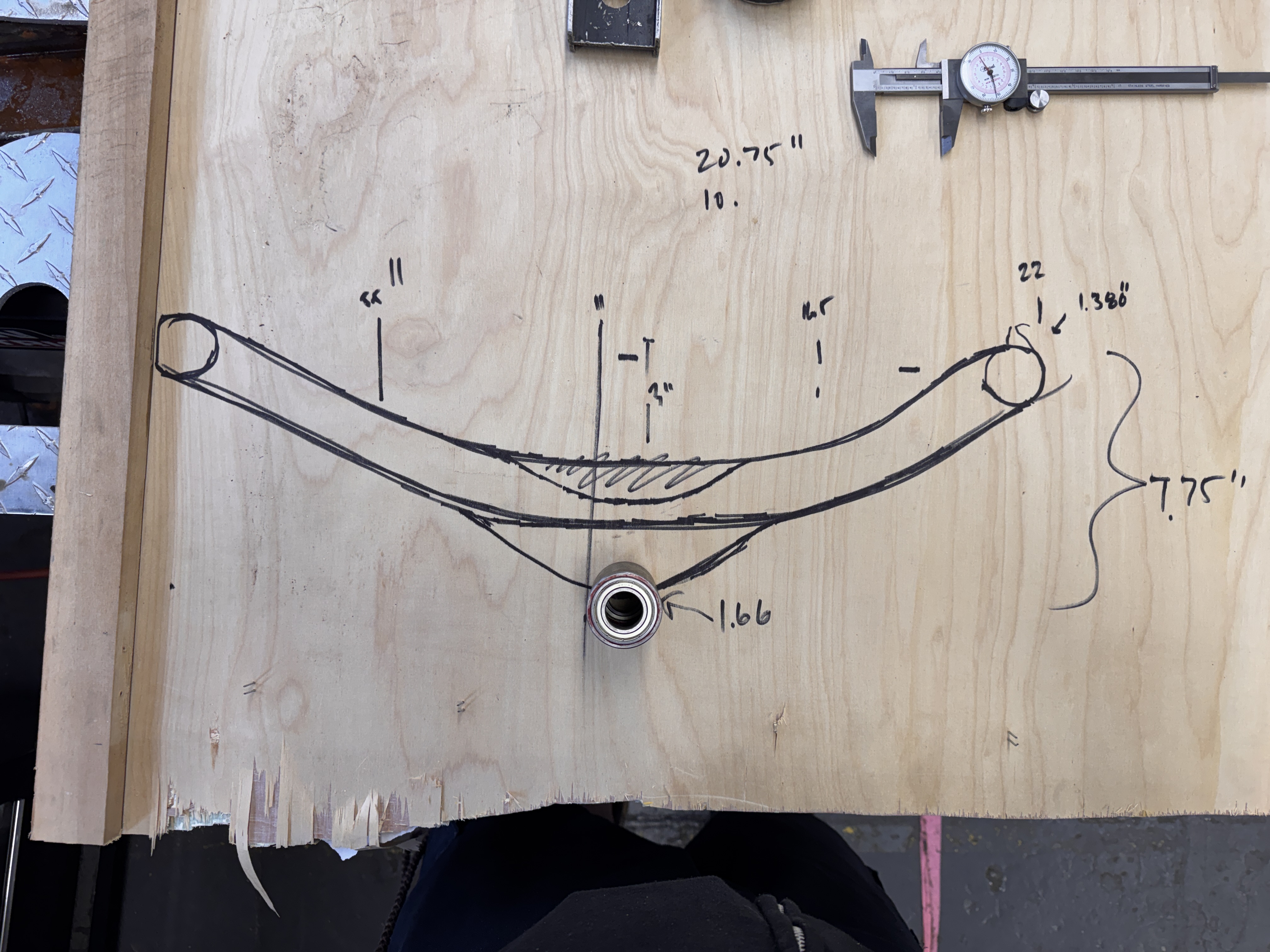
TIE RODS — CHROMOLY, GRADE 8, BUILT RIGHT
Tie rods were manufactured from tubular chromoly steel with grade 8 hardware and threaded rod ends. The plywood layout sketch on the build table — visible in the shop — kept everyone honest on length and angularity before any cutting happened. Both rods are adjustable for toe; the threaded end fittings give us real alignment capability at the track.
Material: Chromoly steel tube (4130)
Hardware: Grade 8 fasteners throughout
End fittings: Threaded rod ends — adjustable toe
Layout method: Full-scale plywood drawing + calipers
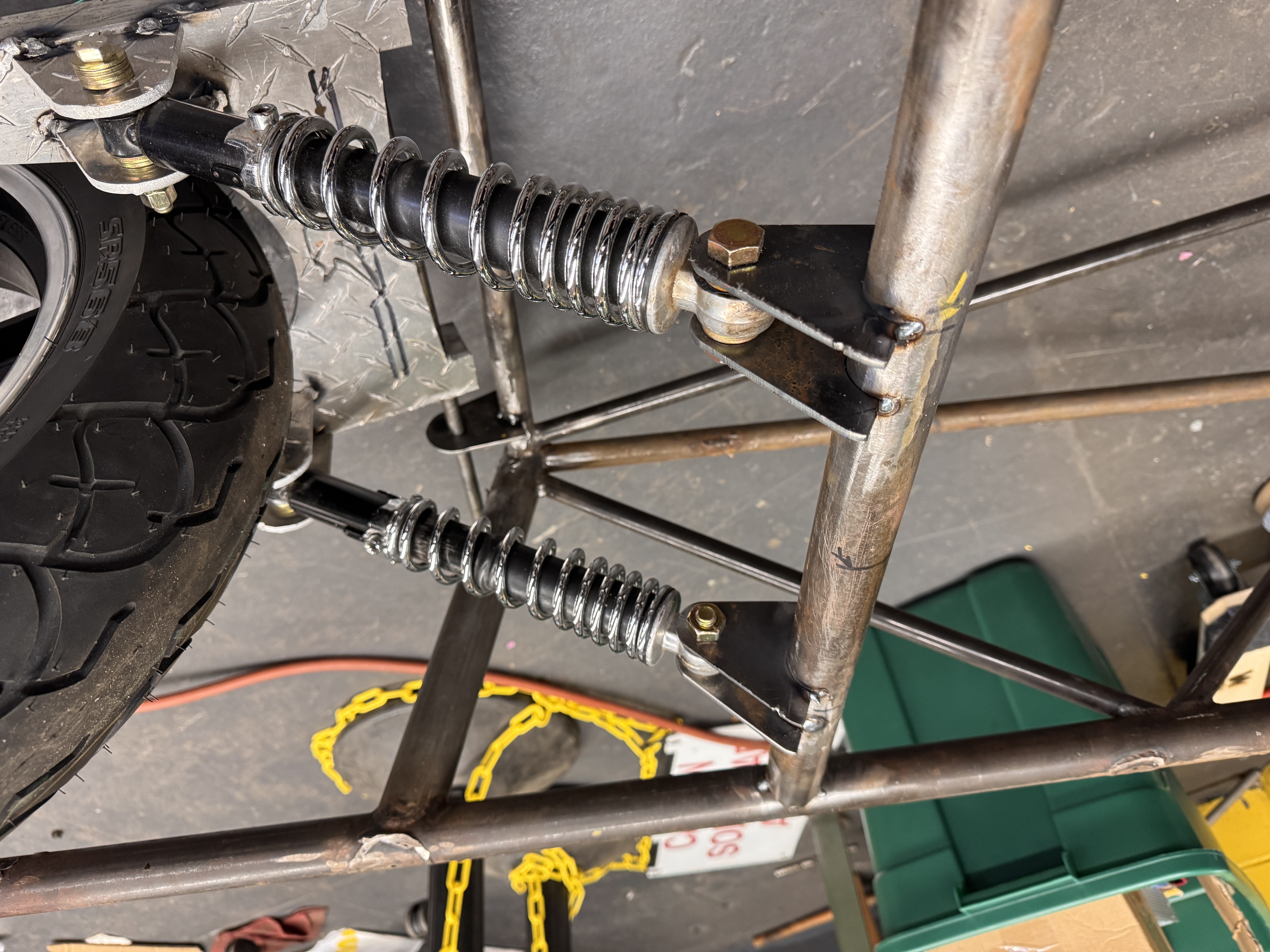
FINAL SHOCK MOUNTS WELDED. GEOMETRY DIALED.
The rear shock mounts are now fully welded in final position. After installation, we adjusted the rear end to remove gross toe-out and camber from the drive wheel — both were visually obvious and now corrected to a usable baseline.
We also opened a discussion on adding threaded adjustment to the rear geometry — a turnbuckle or eccentric bolt arrangement that lets us dial toe in real-time during the race without pulling tools. That design work is on the task list for next session.
ACCELERATOR MOCKUP & THE SEAT PROBLEM
We mocked up the accelerator pedal position with the driver in the car — always. Rear suspension coilovers installed Motor and rear assembly overview more informative than doing it on paper. This also surfaced a real issue: we have drivers ranging considerably in size, and the fixed seat position that works for one doesn't work for another.
An adjustable seat is now on the engineering backlog. Whether that's a sliding rail system or a modular foam/insert approach is TBD, but it needs to be resolved before we're fighting geometry at the event.
TEAM PROCESS NOTE: We identified a recurring pattern this session: technical discussions were getting deep and productive, then drifting before landing on a decision or clear next step. Starting next meeting, we're implementing a simple protocol — every discussion that goes longer than ~5 minutes needs to close with either a recorded decision or a named action item. That's it. No more spinning in the same orbit.
PIER 76 SPECIAL — SIX PIES DEEP
STATEN ISLAND PIZZA ROYALTY · REDUCED RATE FOR THE TEAM · NO LEFTOVERS REPORTED
OPEN ITEMS HEADING INTO NEXT SESSION
Geometry tuning: Design threaded rear toe/camber adjuster
Seat: Design and build adjustable driver seat
Steering: Final welds on column and bracket after geometry check
Pedals: Finalize accelerator pedal position and fabricate mount
Process: Implement discussion → decision protocol at all meetings
Project Manager:
Thomas Smolka
Email:
seagullsolarsi@gmail.com
Telephone:
718-614-4835
Address:
101 Belmont Pl, Staten Island, NY 10301